
Intro:
This past week I was asked by my grammar school science teacher if I would stop by his class and show off a cool project that would inspire his students, just like I had last year. Though it was short notice (he only told me 3 day before he wanted me), I told him that I would love to come and show off a cool project, though I did not have one. I told him this to which he said that was not a problem and anything I brought would be fine. This was good to hear but still left me with nothing to bring.
At first I thought of bringing an old robot that I had built in college back to life, but after spending most of Saturday on it, I knew that there would be no way for me to have it finished for Monday (I will fix it one day soon and post about it here). Now I was back to where I was a day earlier, with nothing to show. The only thing I did know was that whatever I was going to make needed to be interactive and interesting. I wanted the students to be inspired to create projects of their own.
I sat around for a little while and out of nowhere I was hit with an idea. The idea was a tilt maze game, something like Labyrinth but controlled with an Arduino.
The Build:
I started with a big cardboard box I had laying around. What I wanted to build was a floating platform that was suspended by a free floating ring. This was then attached to the frame of the whole game (See the diagram below for a better idea of what I mean). The platform would be in the center which is connected to the ring at two points in the center. From there the ring would connect to the frame at its center on a different side. This allows the center to move one way while the ring can move another. The platform can move back and forth, left and right.
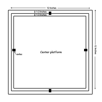
I drew out a twelve inch by twelve inch box, then inside that box, I drew a second box one half inch smaller. Then I repeated this process one more time so I had three squares. Using a hobby knife, I cut the three squares out and then trimmed a little over 1/8 of an inch off the two inter squares to give them room to freely move within themselves.
Once this was done, I took some balsa wood and reinforced parts on the outer frame and ring. With some more balsa wood I made eight little blocks and drilled a hole through the center. I cut up some paper clips using a wire cutter and made axles that connected the three squares together in the above mentioned way.
Then I made a twelve inch by twelve inch base and eight, four inch tall strips which would allow me to connect the top frame to the bottom.
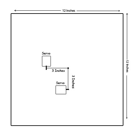
Mounted to the base, I placed to servo motors at a ninety degree angle from each other, with the center of there output shafts that are three inches from the center of the base (Look at the diagram below to get a better idea what I mean). Using a little solid core wire I connected the servos to the top center section to pivots that where also attached three inches from the center at a ninety degree angle to each other.
With all that complete, I got started on the control system. I wanted this game to be very interactive and I thought the best way to do that is by using a WiiChuck. The WiiChuck is a great little device that have a lot of cool parts inside of it, one part being a 3 axis accelerometer.
I have already used the WiiChuck before in another project, so I have a lot of code written for it along with a good understanding on how to use it. What was new to me in this build, was that I used Adafruit’s 16 channel PWM controller. I used this breakout to control the two servo motors, which moved the top platform. This was not 100% needed though it was a great learning experience for future projects.
Using some of the code from my WiiMouse project, I took the X and Y accelerometer data from the WiiChuck and then using the Map function, converted the output to be from 0-180 degrees. This allowed me to control both servos by assigning one to the X accelerometer and the other to Y. Later, while demonstrating the game for the class of students, I added a feature that would disable the controller input when the C button was pressed so you could set the controller down without the platform moving around.
The WiiChuck and Adafruit PWM board both use the I2C protocol and they both have different addresses. This allowed me to chain all the connections together and use the SDA and SCL pins on my Arduino Uno R3. This can be seen below.
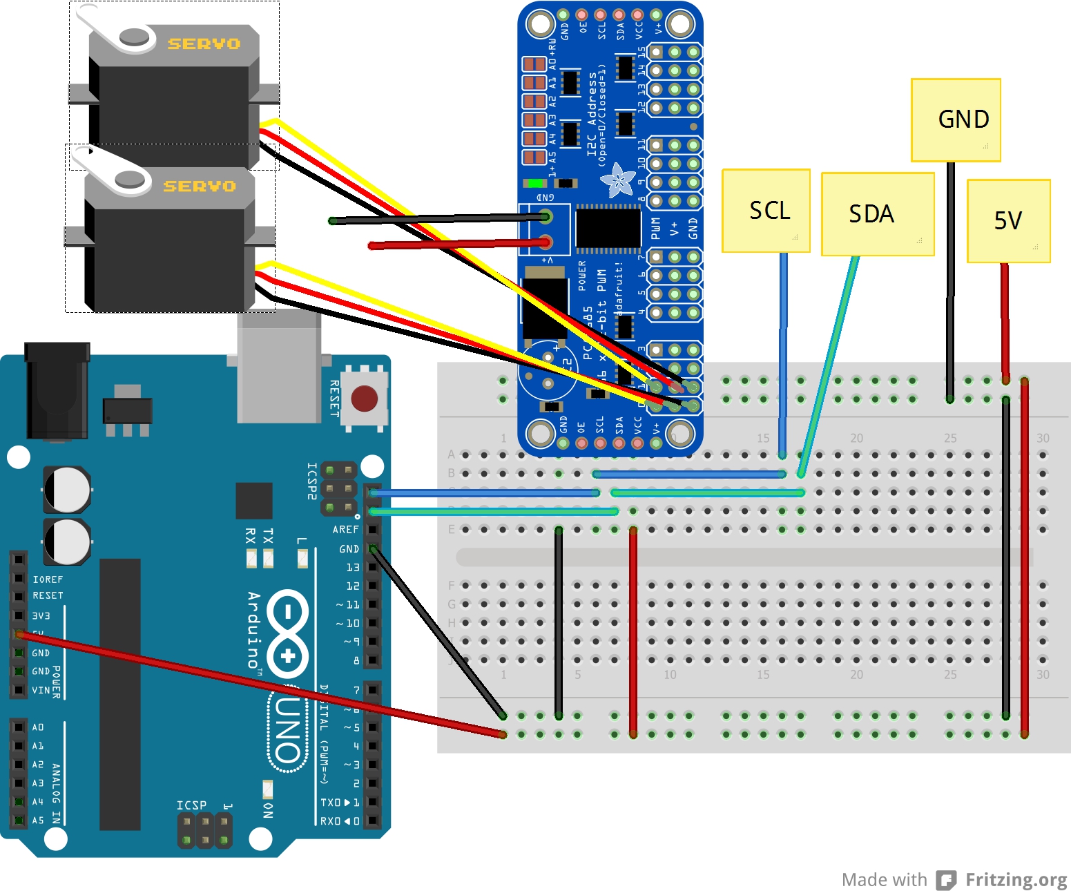
When it came to powering the game, being that I was short on time, I used the USB jack on the Arduino for its own power along with supplying power to the WiiChuck and PWM board. To power the servos, I used my bench power supply (made from an old computer power supply), to provide the 5 volts needed. I did this, so the servos would receive the proper amount of current needed to drive them without effecting the Arduino.
Code
For this project I Used Adafruit’s, Adafruit_PWMServoDriver libary* which can be found HERE
The PWM/Servo Driver can be found HERE
The Code for the Maze game can be found at my GitHub HERE
*(When I get some more time, I’ll will write a second copy of the code to not require the PWM board for people who want to build a similar project but without needing as many parts)
Media
Here is a video showing the Maze in action along with some photos.


